
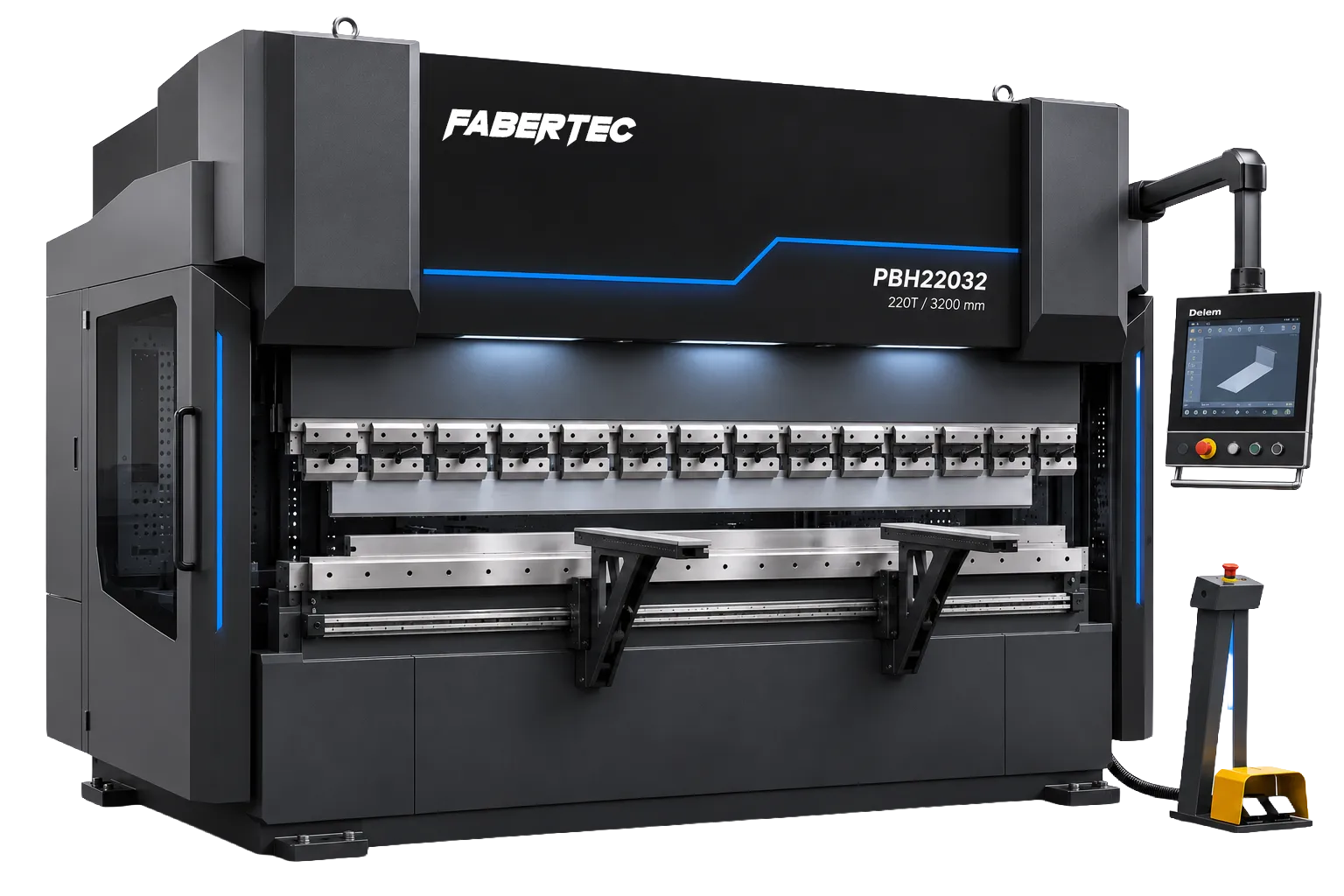
The Fabertec PBH Series is a range of CNC hydraulic press brakes for sheet-metal and plate fabrication. The range covers compact machines for brackets and folded panels, as well as longer beds for channels, frames and heavier fabrication work.
On the servo-hydraulic models, a servo motor drives the hydraulic pump on demand. The hydraulic cylinders move the upper beam, while independent Y1 and Y2 controls track its position on both sides of the machine. The CNC backgauge positions the sheet for each bend, and the operator can save the programme for the next batch.
The right model depends on the material grade, thickness and longest bend. For example, the PBH11032 and PBH22032 both have a 3,200 mm bending length. The PBH22032 provides twice the bending force for jobs that need more pressure over the same length.
Fabertec Hydraulic Press Brake Models
| Model | Bending force | Bending length | Purpose |
|---|---|---|---|
| PBH8020 | 80 tonnes | 2,000 mm | Compact model for brackets, channels and general sheet-metal work. |
| PBH11032 | 110 tonnes | 3,200 mm | Longer bed for folded panels and channels up to 3.2 m long. |
| PBH16032 | 160 tonnes | 3,200 mm | Higher bending force for medium-heavy fabrication on a 3.2 m bed. |
| PBH22032 | 220 tonnes | 3,200 mm | Heavy fabrication jobs requiring more bending force over the same length. |
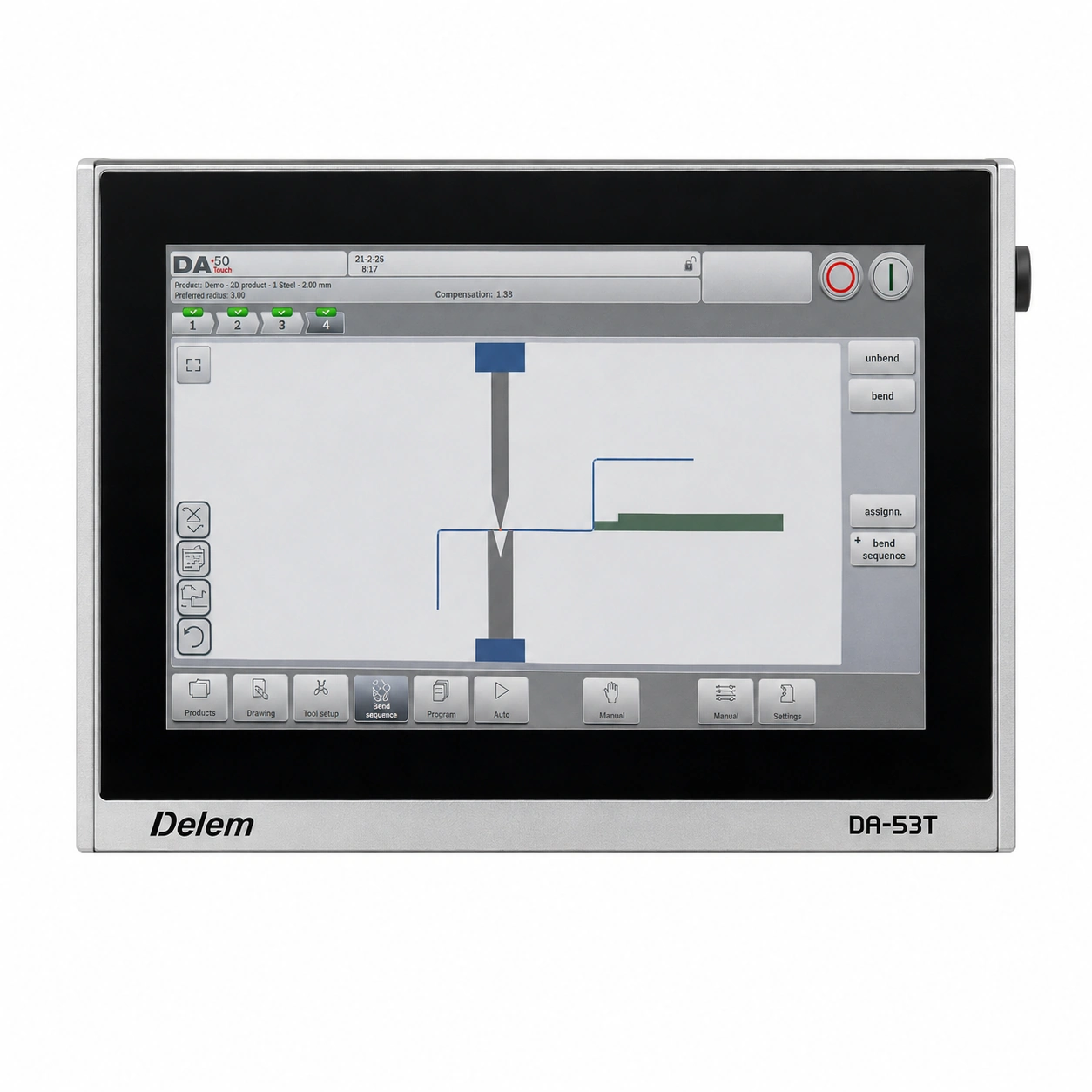
Delem DA-53T
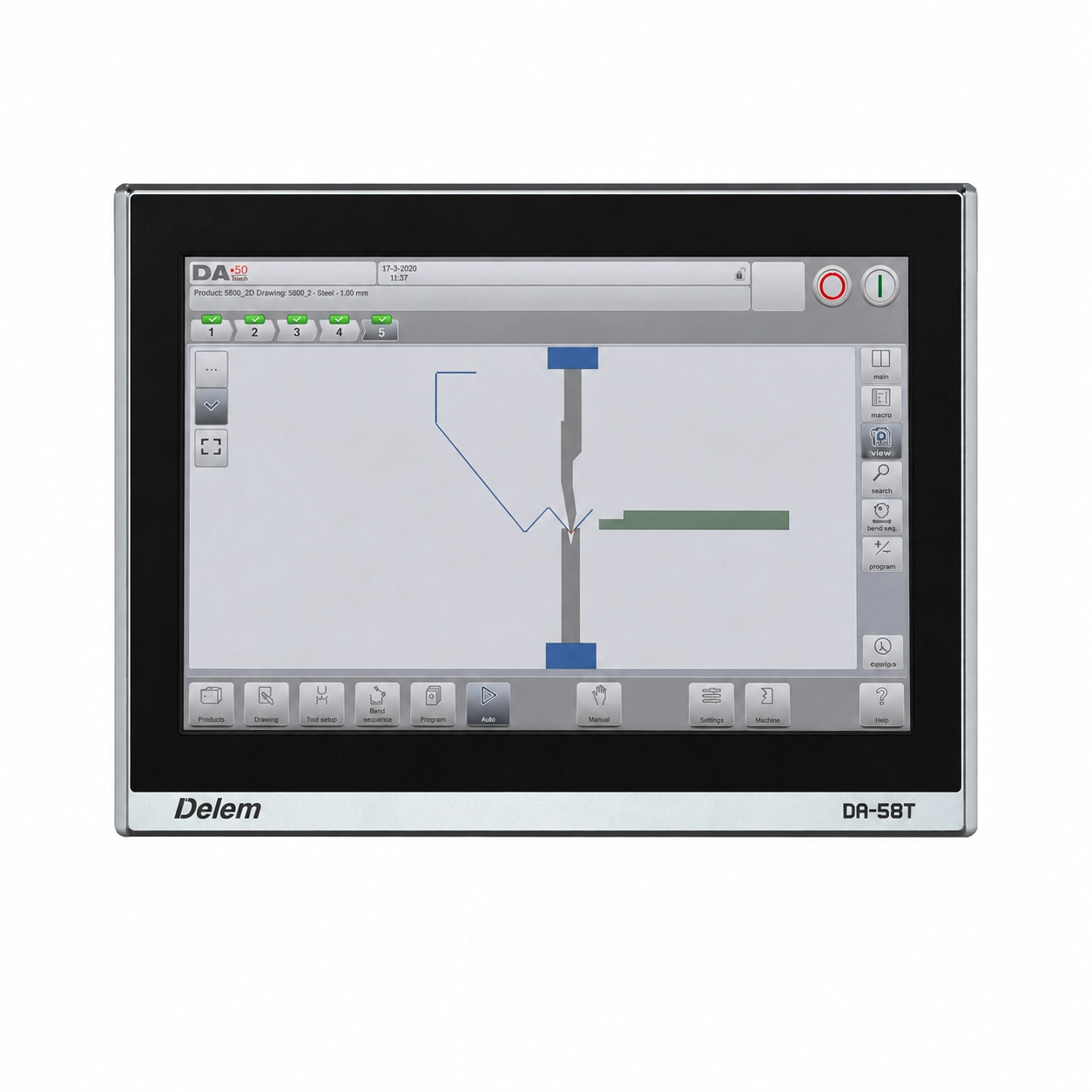
Delem DA-58T
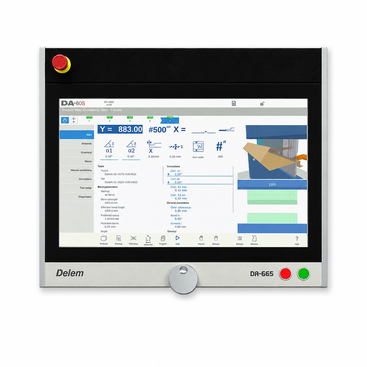
Delem DA-66S
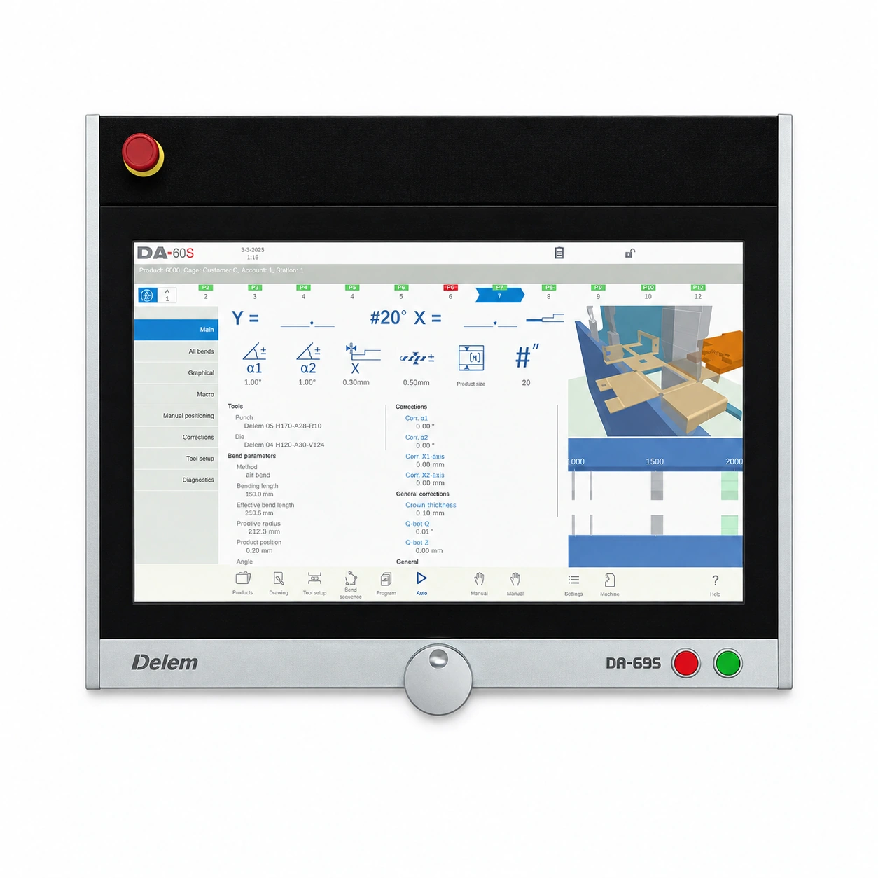
Delem DA-69S
Technical Specification
| Specification | PBH hydraulic press brake range |
|---|---|
| Bending force | 80, 110, 160 or 220 tonnes across the four core models. |
| Bending length | 2,000 mm on the PBH8020. The PBH11032, PBH16032 and PBH22032 have a 3,200 mm bed. |
| Main drive | Servo-driven hydraulic pump on the core models. |
| Upper beam control | Independent Y1 and Y2 control with linear scales measuring the ram position on each side. |
| Backgauge | X and R axes as standard. Optional Z1 and Z2 axes position each gauge finger independently along the bed. |
| Tooling and clamps | European-style segmented tooling with quick-release upper clamps. |
| CNC crowning | Available on applicable models to compensate for deflection along the bend. |
| Working dimensions | Ram stroke, daylight, throat depth and distance between uprights are subject to confirmation for each model. |
Backgauge and Tooling
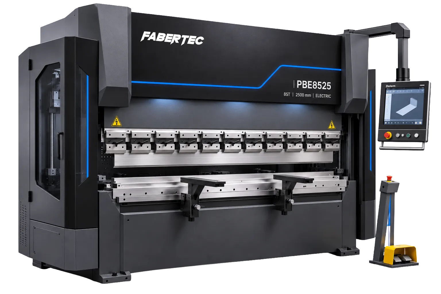
The X-axis sets the distance between the bend line and the gauge fingers, which determines the flange depth. The R-axis adjusts the finger height. Optional Z1 and Z2 axes let each finger move sideways independently, which is useful when a part has an uneven edge or needs a different gauging position for the next bend.
European-style segmented tooling lets the operator combine punch sections to match the length of the part. For channels and boxes, a gooseneck punch can give an existing flange room to pass during the next bend. On longer parts, CNC crowning helps keep the bend angle consistent from the centre of the workpiece to the ends.